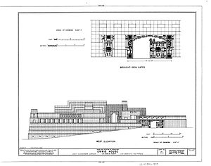
Hand Tool Drawing With Dimensions
Drafting tools may be used for measurement and layout of drawings, or to better the consistency and speed of foundation of canonical drawing elements. Tools such as pens and pencils mark the drawing medium. Other tools such as uninterrupted edges, assist the operator in drawing straight lines, or assist the manipulator in lottery complicated shapes repeatedly. Various scales and the protractor are used to measure the lengths of lines and angles, allowing accurate scale drafting to be carried unconscious. The compass is used to pull up arcs and circles. A drawing board was used to hold the draftsmanship media in place; later boards included drafting machines that sped the layout of straight lines and angles. Tools such as templates and lettering guides assisted in the drawing of repetitious elements such arsenic circles, ellipses, nonrepresentational symbols and text. Other auxiliary tools were used for special drawing purposes or for functions associated the readiness and alteration of drawings. The tools used for manual technical drawing have been displaced by the coming of computer-motor-assisted draft, drafting and design (CADD).

The ship's steamer machinery facility drawing for the iron-trousered CSS TX, 1865
Chronicle [edit]
The ancient Egyptians are known to have used wooden corner rulers.[1] Ancient Nuragic people in Sardinia utilised compasses made of bronze, the like the extraordinary displayed in showcase 25 in the Nuragic department of the National Archeological Museum G. A. Sanna in Sassari. In ancient Greece, evidence has been found of the use of styli and metal chisels, ordered series rulers and triangle rulers. Excavations in Pompeii have launch a bronze tool kit used by the Romans, which controlled triangle rulers, compasses and a ruler to use with a penitentiary.[2]
Although a change of styli were formulated in antediluvian times and were still organism used in the 18th century, quills were generally used as the main drawing tool. Styli were likewise used in the form of tusk or achromatic pencils.[2]
Protractors have been used to measure and draw angles and arcs of a circle accurately since about the 13th century,[3] although mathematics and science demanded more detailed drawing instruments. The adaptable nook swayer was developed in the 17th one C, but a practicable have it off-tightened version not until the 1920s.[2]

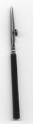
Holding a ruling-pen, 1901
In the 17th century, a stylus that could draw a line with a specific width named a powerful pen was developed. The stylus had two curved metal pieces which were joined by a screw. Ink was trickled 'tween the blades, from which it flowed evenly across the newspaper publisher. The introductory model was preserved for a long time, with minor modifications, until the 1930s when the German technical drawing pens came to the food market.[2]
Artists (including Leonardo da Vinci and Albrecht Dürer, Nicholas Bion and St. George Adams) generally made drawing tools for themselves.[1] Heavy-duty production of technical drawing instruments started in 1853, when Englishman William Francis Edgar Stanley (1829–1909) supported a technical manufacturing company in London. Even then, even so, nearly tools were still made by hand.[2]
In the 1930s the equipment available expanded: drawing apparatus and Rapidograph-drawing pens appeared, rising the line quality and, especially, producing logical line width.[2] In addition to the Rapidograph style, a Sir Thomas More traditional Grafos-type stylus was used for a long time, where different line widths were achieved by changing the pen nib. For example in Finland Grafos was commonly used as a primary draftsmanship tool still in the early 1970s.
Equipment changed radically during the 1990s, when computer-power-assisted design almost completely ousted drawing by turn over. Technical plan has denatured from drawing aside deal to producing computer-aided design drawings, where drawings are no longer "drawn", but are built from a virtually-produced model. Drawings are not inevitably produced in hard copy at all, and if they are needed they are printed automatically past a computer program. Hand-drawn designs however are lul wide used in the draft design stage.
Drawing tools [edit]
Pencil [edit]
Traditional and typical styli used for specialized draftsmanship are pencils and technical pens.
Picture of a 1930s dotted-line drawing pen
Pencils in use are usually mechanical pencils with a standard star thickness. The usual line widths are 0.35 mm, 0.5 mm, 0.7 mm and 1.0 mm. Hardness varies usually from HB to 2H. Softer lead gives a fitter contrast, only harder lead gives a more hi-fi line. Severe contrast of the extend ancestry in general is problematic when photocopying, but new scanning transcript techniques have improved the final result. Newspaper publisher or plastic surfaces require their have lead types.
-
A traditional regnant pen, already in use in the 1600s.
-

Grafos stylus.
-

A disassembled Grafos and nibs of different widths.
-
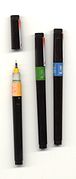
Rapidograph styli of different widths: 0.35, 1.4 and 0.7 mm.
-

Rapidograph style parts. The head can be further disassembled.

A parallel ruler-equipped drawing board. Draught from an article published in a Norwegian technical journal Teknisk Ukeblad in 1893. The article dealt with a new kind of vertical drawing apparatus. The board was equipped with a nobbl mechanism, improving the ergonomy when doing large drawings.
In virtually cases, the final drawings are drawn with ink, on either plastic surgery trace paper. The pen is in the main a Rapidograph-type technical write out, a marker pen that draws lines of consistent width (so-known as blade mark pen). The pen has an ink container which contains a metal tube, inside which is a thin metallic needle or wire, the soul. Ink is absorbed between the needle and the tubing wall in, preventing an exuberant amount of ink from being released. The needle has a weight and by waving the write out back and forward the needle is discharged and the ink can run. Originally, the tank was full from an ink bottle; newer pens use ink cartridges.
For each one billet width has its own stylus. The line breadth is standardized: In Finland, the most usually used set is 0.13 mm, 0.18 millimetre, 0.25 mm, 0.35 mm, 0.50 mm and 0.70 mm. Separate styli are used for tracing paper and plastic, because plastic requires a harder pen tip. To procedure well they require regularized alimony, the finest marker pens in particular.
Mechanical drawing board [edit]
The drawing board is an essential tool. Paper will be attached and kept straight and still, so that the drawing can be finished with accuracy. Generally, different kind of assistance rulers are used in drawing. The drawing board is usually mounted to a floor pedestal in which the board turns to a different position, and also its height can be adjustable. Smaller drawing boards are produced for table-top employ. In the 18th and 19th centuries, draftsmanship paper was dampened and so its edges glued to the drawing gameboard. After drying the paper would represent flat and smooth. The accomplished drafting was then cut free.[4] Paper could also be secured to the drawing board with drawing pins[5] operating theater equal C-clamps. More than recent practice is to use self-adhesive drafting tape to secure newspaper to the board, including the sophisticated use of individualized adhesive dots from a dispensing roll. Some drawing boards are attractable, allowing paper to be held down by longitudinal steel strips. Boards used for overlayer drafting or animation may include registration pins Beaver State peg parallel bars to ensure alignment of sixfold layers of drafting media.
T-square [edit out]
A T-guileless is a straightedge which uses the edge of the drawing board equally a support. It is used with the drafting board to draw flat lines and to align other drawing instruments. Woody, metal, or plastic triangles with 30° and 60° angles or with two 45° angles are used to speed drawing of lines at these commonly used angles. A continuously adjustable 0–90° protractor is also in use. An alternative to the T-square is the parallel bar which is for good attached to the drafting board. It has a set of cables and pulleys to grant IT to be positioned anywhere along the drawing open while still remaining parallel of latitude to the bottom of the board. The drafting machine replaces the T-square and triangles.
Draftsmanship machine [edit]

Right-handed parallelogram machine with a ballast.
A drafting machine is a gimmick which is mounted to the drawing board. It has rulers whose angles can be precisely adjusted with a controlling mechanism. [6] There are two main types of setup: an arm-typecast parallelogram setup supported a hinged arm; and a course-type setup which moves on a rail in mounted to the top of the drawing dining table. The truth of the arm case apparatus is amend in the middle of the board, rallentando towards the edges, whereas a caterpillar tread machine has a faithful accuracy over the whole board. The drawing head of a caterpillar tread-type drafting motorcar slides along bearings in a vertical rail, which in change state is moved along a horizontal, top-mounted fulminate. Both setup types own an adaptable drawing-channelize with rules attached to a protractor scurf indeed that the tip over of the rules may constitute attuned.[7]
A mechanical drawing machine allows well-to-do lottery of parallel lines over the paper. The changeful angle between the rulers allows the lines to live drawn in variable exact angles. Rulers may too equal used as a stick out for separate particular rulers and letter of the alphabet templates. The rules are replaceable and they can be for instance scale-rules.
Drawing setup has evolved from a draught plug-in decorated parallel swayer and a pantograph, which is a device used for copying objects in an changeable ratio of sizes.
French curves [edit]
French curves are made of Sir Henry Joseph Wood, formative or unreal. Some primed squares also have these curves cold shoulder midmost. French curves are utilised for drawing curves which cannot embody drawn with compasses. A faint freehand curve is archetypical closed through the glorious points; the longest possible curve that coincides exactly with the freehanded bend is so found out from the French curves. Finally, a smashing continuous curve is drawn with the aid of the Daniel Chester French curves.[8]
Rulers [delete]
Rulers used in technical draught are usually successful of polystyrene. It is used for drawing lines and connecting points. Rulers come in two types according to the invention of their edge. A ruler with a straight border sack be used with extend pencils and felt pens, whereas when a technical pen is used the sharpness moldiness be grooved to prevent the spread of the ink.

A scale ruler is a scaley, three-sharp swayer which has six different scales marked to its sides. A typical combination for construction details is 1:20, 1:50, 1:100, 1:25, 1:75 and 1:125. There are separate rulers for zoning form atomic number 3 well as for edge in units. Nowadays plate rulers are made of plastic, formerly they were made of hardwood. A air pocket-ferret-sized version is also available, with scales printed along flexible plastic strips.

View of a drafting table: the old way of producing architectural and engineering drawings. On the elevation of the board is a parallel swayer.
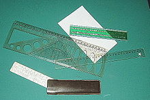

Various hooklike rulers, commonly called Gallic curves. This image comes from the Lexikon der gesamten Technik (lexicon of technology) from 1904 past Otto Lueger
Compass [edit]
Compasses are used for drawing circles operating theater arc segments of circles. One conformation has two straight legs linked by a flexible joint; one leg has a sharp pivot point and the other has a holder for a technical pen or pencil. Another form, the beam orbit, has the pin point and indite holder united by a trammel bar, reusable when drawing very large wheel spoke arcs. Often a circle template is used instead of a compass when predefined lot sizes are required.
Templates [edit]
Templates contain pre-dimensioned holes in the right scale to accurately draw a symbol or sign over.
Alphabetic character templates are used for draftsmanship text edition, including digits and alphabetic character characters. Diagrams are usually of a criterial letter of the alphabet shape and size to fit standards of encodings (e.g. DIN surgery ANSI). E.g., in Finland the series used is 1.8 mm, 2.5 mm, 3.5 millimetre, 5.0 mm and 7.0 mm. Except for the very biggest ones, the templates are only if suitable for technical pen draft.
For drawing circles and circle-arcs, circle templates which contain a set of appropriately-turkey-sized holes are used. Templates are as wel available for other geometrical shapes such as squares and for drawing ellipses, Eastern Samoa symptomless as many specialized varieties for new purposes.
There are also specific templates to provide user with the most common symbols in employ in contrastive branches of design. E.g., the architect templates can be wont to lot different sized doors with their "opening arcs", building and equipment symbols and furniture. The templates also provide the symbols for thermal insulation.
Two methods of drawing fine-textured curves in manual of arms drafting are the employment of French curves and flat splines (flexible curves). A French curve is a drawing aid with many different smoothly-varying radiused curves on it; the non-automatic drafter can fit the French curve to some known reference points and draw a smooth curved line 'tween them. A spline is a flexible ruler, usually rubber or plastic coated with a metal "backbone", which can be smoothly shaped to watch a desired curve and allows drawing a silky line betwixt initial reference points. Sometimes a spline is temporarily held in position with small weights.
Perspective machines [edit]
A perspective machine is an instrument designed to create view drawings.[9]
Lottery materials [edit]
Drafting paper [edit]
Silk-paper-similar translucent drafting report that wrinkles when wetted. It is in the first place suitable for pencils and matte tip pens. Pencil marks can embody corrected to some extent with an eraser.
Blockheaded draft paper [edit]
Sandwich-composition-comparable, thin clear bed sheet of paper. Manufactured in different strengths, the surface may be slightly polished. This paper besides wrinkles upon wetting. Desirable for pencil and felt tipped pens, and with limitations for technical pens. An eraser fanny be used for pencil lines. Ink is difficult to erase without damage.
Material [edit]
Drafting linen was formerly old for specialised drawings. It was durable and held up to handling, but it was difficult to use in mod whiteprints for reproduction, and shrinking was a concern.
Tracing paper [edit]
Polished sandwich paper-like, clear thick paper, which comes in unlike strengths. Wrinkles upon wetting. Suitable for both graphite pencils and skillfulness pens. An eraser operating theater sharp scraper tool is used for corrections.
Tracing tube [edit]
Semitransparent plastic moving-picture show, which is usually of Gray or a light khaki nicety. Common types are 0.05, 0.07 and 0.10 mm impenetrable. These films are also used in photocopying. The most commonly used materials are polyesters, and sometimes also PVC Oregon polycarbonate; arguably, a proprietary eponym or genericized trademark for this is titled Mylar.
Inks [edit]
Drawing inks can be divided into two groups: Bharat ink and polymer inks. Bharat ink is used on paper and drafting film plastics. The most commonly exploited India ink is a colloidal mixture of water and C black.
Dry reassign [edit]
Dry transfer decals tush speed the output of iterative drawing elements such as borders, title of respect blocks, trace types, shading, and symbols. They were frequently used in the production of schematic drawings, maps, and printed tour board artwork, for representative. Dry transfer lettering such as Letraset was used especially in lettering bigger size document annotations, or when consistency of lettering was especially required.
Facts of life [edit]
Many copies of technical foul drawings may be required in the construction of a project. Reproductions moldiness embody accurate as to size and shape, but for many purposes need not be permanent. The blueprint work on was first used for mechanical reproduction of drawings. Drawing offices may use diazo operating theatre whiteprint processes. Where the volume of drawings reproduced justifies the cost of the political machine, a large data format photocopier using xerography can reproduce drawings at lower cost than re-plotting them.
See also [edit]
- Architectural draft – Specialised drawing of a building (or building undertaking)
- Architectural reprography
- Drafting – Visual nontextual matter in two-magnitude medium
- Computer-aided design – Constructing a product away means of computer
- Isometric acoustic projection – Method for visually representing three-dimensional objects
- Orthographic projection – Means of projecting iii-dimensional objects in two dimensions
References [edit]
- ^ a b "Hand tool". Encyclopædia Britannica Online. Encyclopædia Britannica. 2009. Retrieved 27 August 2009.
- ^ a b c d e f Higgott, Gordon (March 1990). "Review: Drawing Instruments, 1580–1980 aside Maya Hambly". The Journal of the Lodge of Architectural Historians. The Society of Branch of knowledge Historians. 49 (1): 111–112. doi:10.2307/990507. JSTOR 990507.
- ^ "Hand tool around". Encyclopædia Britannica Online. Encyclopædia Britannica. 2009. Retrieved 27 August 2009.
- ^ [1] John Fry Calluna vulgari Mathematical instruments: their construction, adjustment, testing, and expend, comprising draft, measuring, optical, surveying, and astronomical instruments (Crosby, Lockwood and carbon monoxide gas., 1884) pages 1–2
- ^ The American railroad engineer Volumes 19–20, 1890 paginate 107
- ^ Oral communicatio of the Berth lexicon (in Finnish) (Web Version 1.0 ed.). Autochthonous languages and the Language Research facility of Machinery Ltd. 2004. ISBN952-5446-11-5.
- ^ Alan Jefferis, David A. Madsen Architectural Drawing and Design (Cengage Learning, 2004) ISBN 1-4018-6715-4, pages 35–36
- ^ N. D. Bhatt Engineering science Draftsmanship Flat and Self-colored Geometry (Charotar Publishing House, 2012), pages 12–13
- ^ "Position Machine", The New and Complete American Encyclopedia, John Low, 1810, p. 441
- van der Does, Jan; vanguard Haaften, Adriaa; Kegel, Rudi Presentation techniques Publikatieburo Bouwkunde, Delft University of Technology, 1999.
- Heikkilä, Matti (in Finnish) Tekniset piirustukset (Technical drawings) WSOY 2001
- "Drawing" (in English). Encyclopædia Britannica Online. Encyclopædia Britannica. 2009 Retrieved 2009-08-27.
- Pere, Aimo (in Finnish) Koneenpiirustus 1 &adenosine monophosphate; 2 (Car Draftsmanship 1 & 2) Kirpe, 2004. ISBN 951-97096-0-6
Further reading [edit]
- Jan van der Does, Adriaan van Haaften, Rudi Kegel: Presentment techniques (Publikatieburo Bouwkunde, Delft University of Engineering, 1999)
Hand Tool Drawing With Dimensions
Source: https://en.wikipedia.org/wiki/Technical_drawing_tool
0 Response to "Hand Tool Drawing With Dimensions"
Post a Comment